Crossover Amplifier
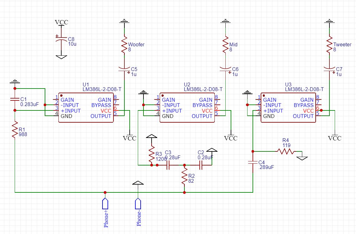
In Winter term 2019, I was taking the Fundamental Electrical course where my teammate and I got to design filters with amplifier for speakers. The goal in this lab was to design and build a functioning 3-range speaker system (high range, low range, and mid-range) using a high pass, low pass and band pass filter with an amplifier for each of the filters. It was to gain more understanding of how a filter works, how to apply a schematic to build a circuit on a breadboard or solder it onto a perfboard.

We start by calculating the cut off frequency for each filter base on audible range for human. We then use the biggest ceramic capacitor we can get so that our resistor value can be low. The resistor value is calculated using R=1/(2pifC). The biggest ceramic capacitor we have at hand are 0.33 microF. With the calculated R, we try to find a resistor network based on the lab supply.
Design Constaints
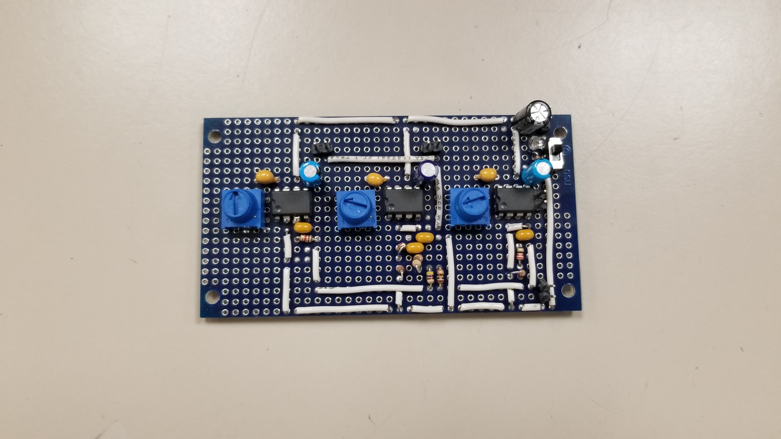
The final product need to utilize 3 LM386s for each output, 4 electrolytic capacitors, 7 ceramic capacitors, resistors, a switch, and a LED. All of these component need to fit on a 9.5cm x 5cm perfboard.Issue 1
Calculation and stimulation were run on LTspice to check the corner frequency at -3dB with off the shelf values for capacitors and resistors.However, we realized that we were not using the real capacitance value, so we need to go back and recalculate with the real capacitance of around 0.28 microF. Real resistance value also taken into account. We end up modifying the resistor network and also rerun the stimulation. After that, we prototype the circuit on a breadboard, and test with the oscilloscope with function generator as the input. The output was expected, so we start adding the amplifier IC LM386 with DC blocking capacitor at the output. The LM386 is powered by a 12V bench power supply. The low pass, and high pass circuit give us somewhat clean noise.
Issue 2
When prototyping with the breadboard, the low pass and high pass circuit give us somewhat clean noise, but the bandpass show some constant frequency no matter the input.We change out different DC filtering capacitor at the output for the mid-IC. However, we still get constant frequency output even without any signal input from the phone. We return the circuit back to the original design. Then a junior student comes over and helps us add a 10microF between the power input for the ICs, and we got clean sound out of the speaker outputs. So …. we forgot to add a decoupling capacitor.

And here is the final product
